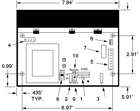
Open Power Supply

- SWITCH - To select the method of controlling the output current: Position (1) The percent Rated Current Potentiometer; Position (2) The 0-10 volt D.C. Input signal.
- SPAN MAX. - potentiometer, sets the 100 percent output current.
- SPAN MIN. - potentiometer, sets the zero output current.
- INPUT CONNECTOR - A.C. mains input and ground (earth).
- OUTPUT CONNECTOR - for brakes & clutches, 0-10 volt input.
- AMMETER CONNECTOR - for (optional) L.C.D. ammeter.
- OUTPUT FUSE - 2 amp, 5 x 20 mm
- 12 OR 24 VOLT SELECTOR SWITCH - Slide the switch towards 12 when using a 12 volt brake or clutch. Slide towards 24 when using a 24 volt unit.
- REMOTE SWITCH - to select the 'On-board Span Max. Potentiometer' or a 'Remote Span Max. Potentiometer'
- REMOTE CONNECTOR - for a 'Remote Span Max. Potentiometer' (for tension adjustments when using the Follower Arm Potentiometer).
Mounting hole spacing = 6.97" x 2.91", Thread = M4-0.7 (Metric)
L.C.D. Ammeter Drawing
Return to Main Page

