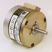
Hysteresis Brake - Specifications & Dimensions

Torque range= 0.4-11 oz.-in. to 9-250 oz.-in.

Patented Cog-Buster keeps slip torque smooth.


Hysteresis Brake Photo Characteristics - Torque is proportional to input current, and independent of RPM.
Torque is especially smooth, even at near-zero RPM. Also good for light tension / high RPM applications, due to good heat dissipation ratings.

Typical Applications - Producing tension for unwinding wire, fiber optic cable, and narrow webs. Also - load simulation for testing electric motors.

Exceptionally Stable & Reliable - Since torque is produced magnetically, across an air gap.

Use the sizing information to select the proper brake.
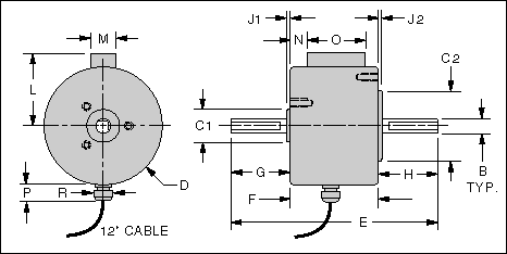
Model H11-1

Hysteresis Brake Specifications
Model
(Click
to view
photo)
Torque
Range
(oz.-in.)
Input
Electric
Power
(watts)
Shaft Inertia
(lb.-in.-sec.2)
Slip Heat
Dissipation

(watts)
Overhung
Load, Max.
(lbs.)
Max.
RPM
Weight
(lbs.)
Data Sheets
(Acrobat
.pdf format)
Cover OnCover Off
H11 0.4 - 11 2 36 x 10-6 9 15 4 9000 0.7 H11 data sheet
H35 0.7 - 35 6 92 x 10-6 15 25 5 8000 2 H35 data sheet
H85 3 - 85 5 560 x 10-6 35 60 40 6000 4.5 H85 data sheet
H140 5 - 140 7 970 x 10-6 45 75 40 5000 6 H140 data sheet
H250 9 - 250 7 290 x 10-5 65 110 50 5000 9 H250 data sheet

Available in 6, 12, 24, & 90 volts D.C.
The Brake Coil Specifications Chart shows rated current & coil resistance.


Brake Dimensions

Specify a solid shaft out 1 side or 2 sides
Hysteresis Brake Drawing Dimensions are in inches.

Model

(Click
to view
drawing)

Shaft
Dia.

Case
Dia.

Shaft-Shaft

Case
Length

Shaft Length

De-Cog Block

Strain Relief

Model

(Click
to view
photo)

B
+/-.0002

D
+/-.010

E
+/-.010

F
+/-.020

G
+/-.020

H
+/-.020
Optional

L
+/-.04

M
+/-.01

N
+/-.03

O
+/-.02

P
+/-.080

R
+/-.020

H11 0.1872 1.80 2.75 1.25 0.75 1.09 0.43 0.28 0.75 0.2 (a) 0.2 (a) H11
H35 0.2496 2.31 3.50 1.75 0.87 1.49 0.57 0.28 1.235 0.35 0.4 H35
H85 0.3746 3.32 4.80 2.30 1.25 1.9 0.70 0.53 1.40 0.55 0.50 H85
H140 3.68 2.09 0.48 H140
H250 0.4996 4.50 5.55 2.80 1.375 2.50 0.81 H250
(a) 2 solder terminals, 68 & 98 degrees clockwise from De-Cog block 'M'. 3" leads with Amp plug. / 12" leads with Amp receptacle


Brake Mounting Holes & Pilot Diameters


Model

No. of
Holes

Thread

Basic Circle

Mounting Pilot Diameter

Mounting Pilot Length

'C1' Side

'C2' Side

C1
+0 / -.0005

C2
+0 / -.003

J1
+/- .005

J2
+/- .005

H11 3 #4-40 0.6875 1.625 0.500 1.000 0.08 0.05
H35 #6-32 0.906 2.000 0.625 1.500 0.08
H85 #8-32 1.500 2.875 0.875 2.250 0.10
H140 3.250
H250 #10-32 1.750 4.000 1.125 3.000 0.125

Return to Main Page