- Adjustable tension - for unwinding (payout) webs
- Load simulation - for testing stepper motors, gear motors and mechanisms
- Soft stops
 |
Typical applications:
|
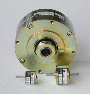
| Models B5Z-1, B150-HA, B1-2 |
 |
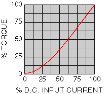
Torque is -
While the load torque is less than the output torque, the brake shaft won't rotate. When the load torque is increased, the brake will slip smoothly at the torque level set by the input coil current. Use the sizing information to select the proper brake. |
Model(Click |
Torque Range (lb.-in.) |
Input Electric Power (watts) |
Shaft Inertia (lb.-in.-sec.2) |
Slip Heat Dissipation (watts) |
Overhung Load, Max. (lbs.) |
Max. RPM |
Weight (lbs.) |
Data Sheets (Acrobat .pdf format) |
|---|---|---|---|---|---|---|---|---|
| B5Z | 0.006 - 0.31 | 1.5 | 16 x 10-8 | 2 | 0.7 | 3500 | 0.2 | B5Z data sheet |
| B1 | 0.04 - 1 | 2 | 11 x 10-7 | 3.5 | 4 | 3000 | 0.6 | B1 data sheet |
| B2 | 0.05 - 2.5 | 3 | 55 x 10-7 | 8 | 5 | 2500 | 1 | B2 data sheet |
| B6 | 0.2 - 6 | 4 | 23 x 10-6 | 15 | 25 | 2000 | 2 | B6 data sheet |
| B15 | 0.3 - 15 | 6 | 34 x 10-6 | 20 | 2.5 | B15 data sheet | ||
| B35 | 0.6 - 35 | 9 | 12 x 10-5 | 30 | 50 | 1800 | 4 | B35 data sheet |
| B60 | 1 - 60 | 8 | 45 x 10-5 | 50 | 100 | 7 | B60 data sheet | |
| B115 | 2.5 - 115 | 13 | 61 x 10-5 | 55 | 120 | 8 | B115 data sheet | |
| B150 | 3. - 150 | 15 x 10-4 | 80 | 1300 | 12 | B150 data sheet | ||
| B220 | 4. - 220 | 18 | 29 x 10-4 | 110 | 1000 | 21 | B220 data sheet |
Available in 6, 12, 24, & 90 volts D.C.
The Brake Coil Specifications Chart shows rated current & coil resistance.
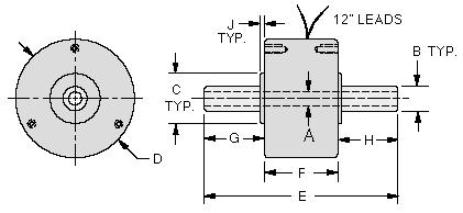
Brake Dimensions - Specify a solid shaft out 1 side, 2 sides, or a hollow shaft
 Dimensions are in inches.
Model(Click |
Thru-Bore |
Shaft Dia. |
Mounting |
Case Dia. |
Shaft-Shaft |
Body |
Shaft Length |
Mtg. |
|
|---|---|---|---|---|---|---|---|---|---|
| A +.001 -0 |
B +/-.0002 |
C +0 -.001 |
D +/-.015 |
E +/-.010 |
F +/-.030 |
G +/-.020 |
H +/-.020 Optional |
J +/-.010 |
|
| B5Z | Solid Shaft Only |
0.1247 | 0.437 | 1.05 | 2.50 | .88 | 0.81 | 0.06 | |
| B1 | 0.1872 | 0.687 | 1.56 | 2.70 | 1.06 | ||||
| B2 | 0.2496 | 0.750 | 2.09 | 3.05 | 1.15 | 0.94 | |||
| B6 | .3746 | 1.186 | 2.47 | 3.54 | 1.37 | 1.09 | 0.08 | ||
| B15 | Solid | 1.125 | 2.87 | 3.56 | |||||
| B15-H | 0.375 I.D. | .498 | 2.10 | 0.47 | 0.27 | ||||
| B35 | Solid | 0.4995 | 3.37 | 3.71 | 1.47 | 1.12 | 0.09 | ||
| B35-H | 0.375 I.D. | 0.498 | 2.20 | 0.47 | 0.25 | ||||
| B60 | Solid | 0.7495 | 1.875 | 4.50 | 3.53 | 1.77 | 1.42 | 0.33 | 0.11 |
| B60-H | 0.501 I.D. | 0.748 | 2.63 | 0.52 | |||||
| B115 | Solid | 0.7495 | 4.71 | 3.53 | 1.41 | ||||
| B115-H | 0.501 I.D. | 0.748 | 2.63 | 0.52 | |||||
| B150 | Solid | 0.7495 | 1.625 (a) | 5.23 | 3.92 | 2.17 | 1.53 | 0.22 | 0.13 |
| B150-H | 0.750 I.D. | 0.906 | 3.187 | 3.25 | 0.82 | 0.26 | 0.09 | ||
| B220 | Solid | 0.7495 | 3.625 | 6.25 | 5.63 | 2.63 | 1.50 | 0.09 | |
| Model | No. of Holes |
Thread | Basic Circle |
|---|---|---|---|
| B5Z | 6 (a) | #1-72 (a) | 0.906 (a) |
| B1 | 3 | #6-32 | 1.350 (a) |
| B2 | 1.350 | ||
| B6 | 2.203 | ||
| B15 | #8-32 | 2.000 | |
| B35 | 4 | #10-32 | 3.000 |
| B60 | 4.228 | ||
| B115 | |||
| B150 | 1/4-20 | 4.812 | |
| B220 | 5.750 |